prototyping a digital pitch-shifting circuit
By Julian Stromer, Feb 5, 2025
A note of credit and appreciation
The project discussed in this article is based nearly entirely on the circuit design and software code posted by Markus Gritsch on dangerousprototypes.com.
The exercise here was to take a fairly advanced electronics project, and to break it down into a step-by-step tutorial for beginners interested in advancing skills by attempting to complete such an exercise. We learned a ton through the process of reproducing Markus' awesome circuit.
Thanks, Markus!
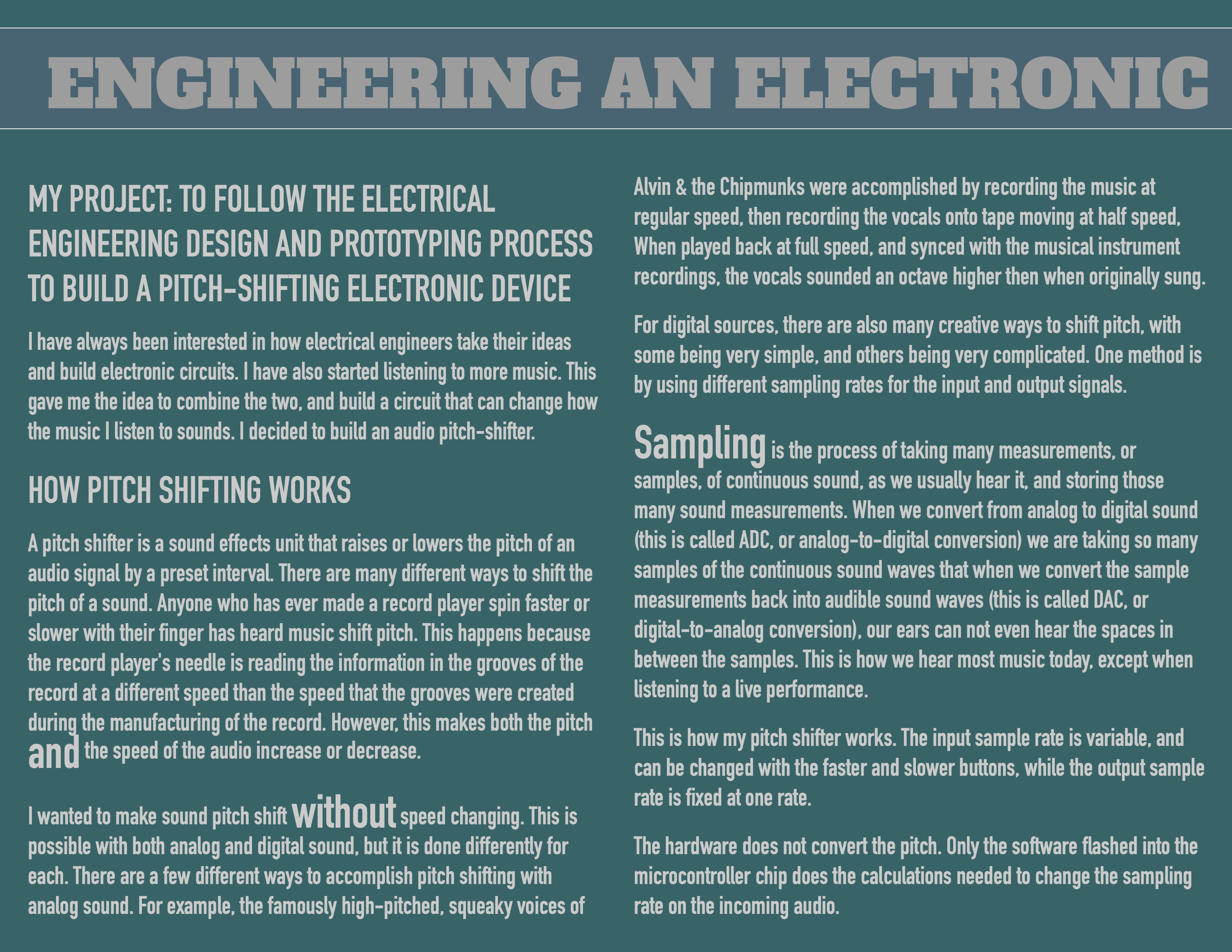
I have always been interested in how electrical engineers take their ideas and build electronic circuits. I have also started listening to more music. This gave me the idea to combine the two, and build a circuit that can change how the music I listen to sounds. I decided to build an audio pitch-shifter.
How pitch shifting works
A pitch shifter is a sound effects unit that raises or lowers the pitch of an audio signal by a preset interval. There are many different ways to shift the pitch of a sound. Anyone who has ever made a record player spin faster or slower with their finger has heard music shift pitch. This happens because the record player's needle is reading the information in the grooves of the record at a different speed than the speed that the grooves were created during the manufacturing of the record. However, this makes both the pitch and the speed of the audio increase or decrease.
I wanted to make sound pitch shift without speed changing. This is possible with both analog and digital sound, but it is done differently for each. There are a few different ways to accomplish pitch shifting with analog sound. For example, the famously high-pitched, squeaky voices of
Alvin & the Chipmunks were accomplished by recording the music at regular speed, then recording the vocals onto tape moving at half speed, When played back at full speed, and synced with the musical instrument recordings, the vocals sounded an octave higher then when originally sung.
Sampling is the process of taking many measurements, or samples, of continuous sound, as we usually hear it, and storing those many sound measurements. When we convert from analog to digital sound (this is called ADC, or analog-to-digital conversion) we are taking so many samples of the continuous sound waves that when we convert the sample measurements back into audible sound waves (this is called DAC, or digital-to-analog conversion), our ears can not even hear the spaces in between the samples. This is how we hear most music today, except when listening to a live performance.
This is how my pitch shifter works. The input sample rate is variable, and can be changed with the faster and slower buttons, while the output sample rate is fixed at one rate.
The hardware does not convert the pitch. Only the software flashed into the microcontroller chip does the calculations needed to change the sampling rate on the incoming audio.
How changing the sampling rate makes pitch shift
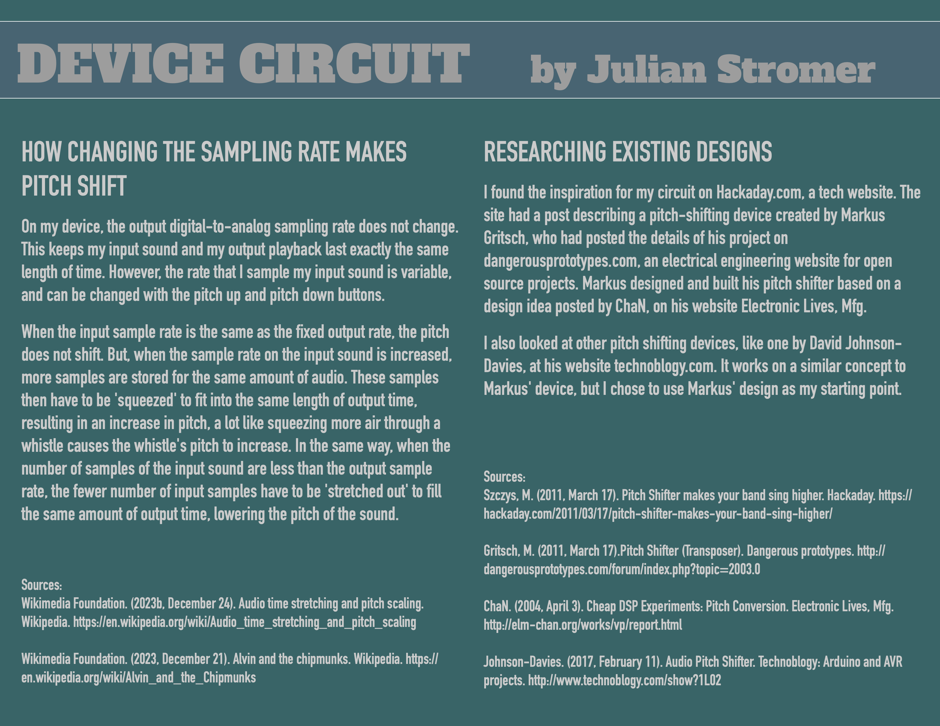
On my device, the output digital-to-analog sampling rate does not change. This keeps my input sound and my output playback last exactly the same length of time. However, the rate that I sample my input sound is variable, and can be changed with the pitch up and pitch down buttons.
When the input sample rate is the same as the fixed output rate, the pitch does not shift. But, when the sample rate on the input sound is increased, more samples are stored for the same amount of audio. These samples then have to be 'squeezed' to fit into the same length of output time, resulting in an increase in pitch, a lot like squeezing more air through a whistle causes the whistle's pitch to increase. In the same way, when the number of samples of the input sound are less than the output sample rate, the fewer number of input samples have to be 'stretched out' to fill the same amount of output time, lowering the pitch of the sound.
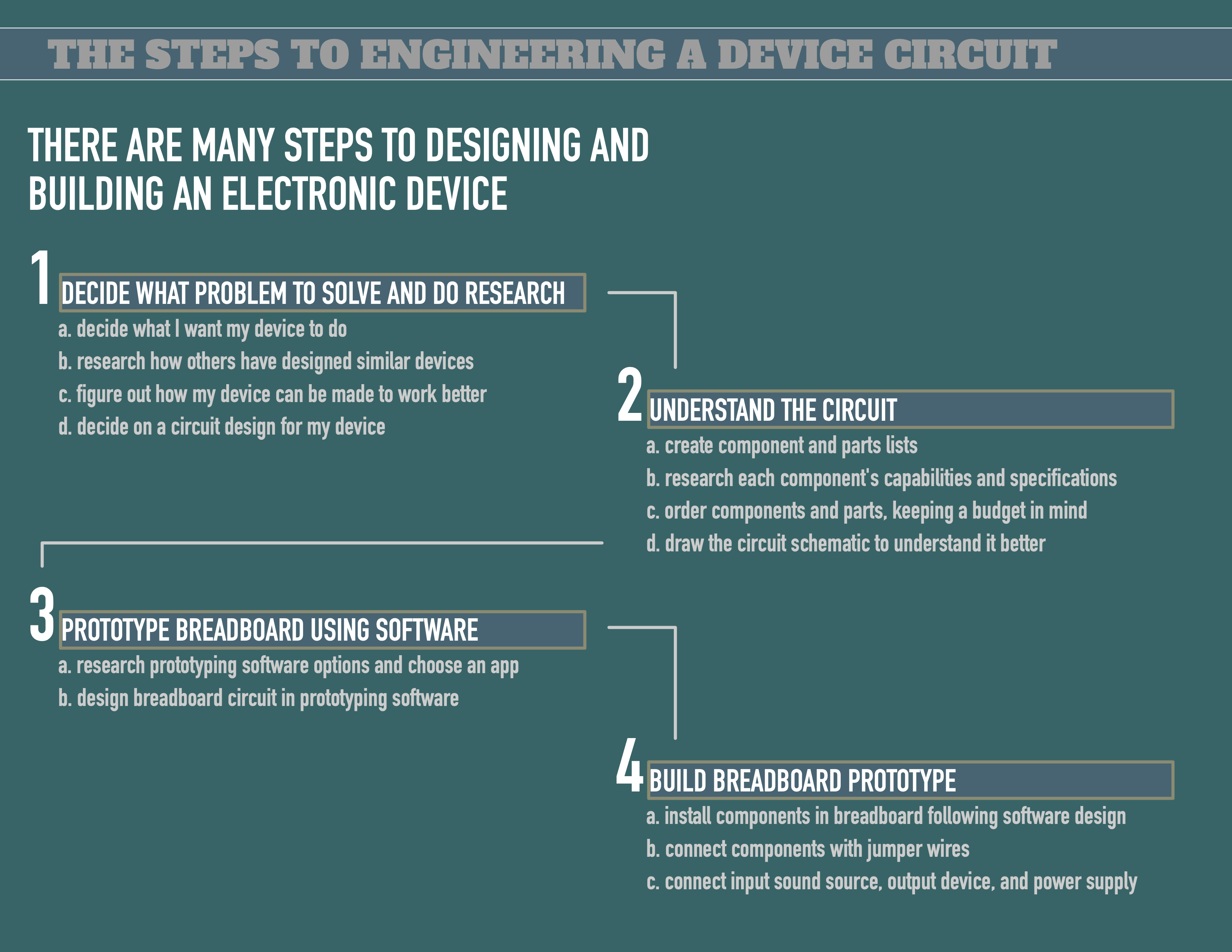
There are many steps to designing and building an electronic device
- 1. Decide what problem to solve and do research
- b. research how others have designed similar devices
- c. figure out how my device can be made to work better
- d. decide on a circuit design for my device
- 2. Understand the circuit
- b. research each component's capabilities and specifications
- c. order components and parts, keeping a budget in mind
- d. draw the circuit schematic to understand it better
- 3. Prototype breadboard using software
- b. design breadboard circuit in prototyping software
- 4. Build breadboard prototype
- b. connect components with jumper wires
- c. connect input sound source, output device, and power supply
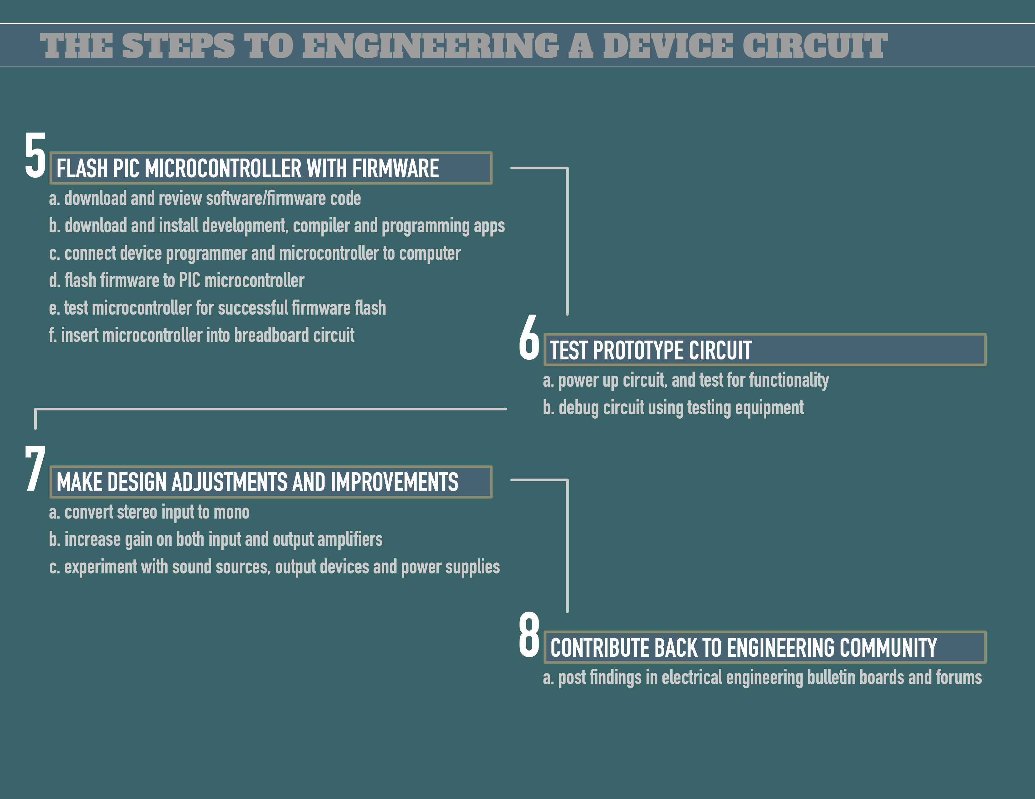
- 5. Flash PIC microcontroller with firmware
- b. download and install development, compiler and programming apps
- c. connect device programmer and microcontroller to computer
- e. test microcontroller for successful firmware flash
- f. insert microcontroller into breadboard circuit
- 6. Test Prototype Circuit
- b. debug circuit using testing equipment
- 7. Make design adjustments and improvements
- b. increase gain on both input and output amplifiers
- c. experiment with sound sources, output devices and power supplies
- 8. Contribute back to engineering community
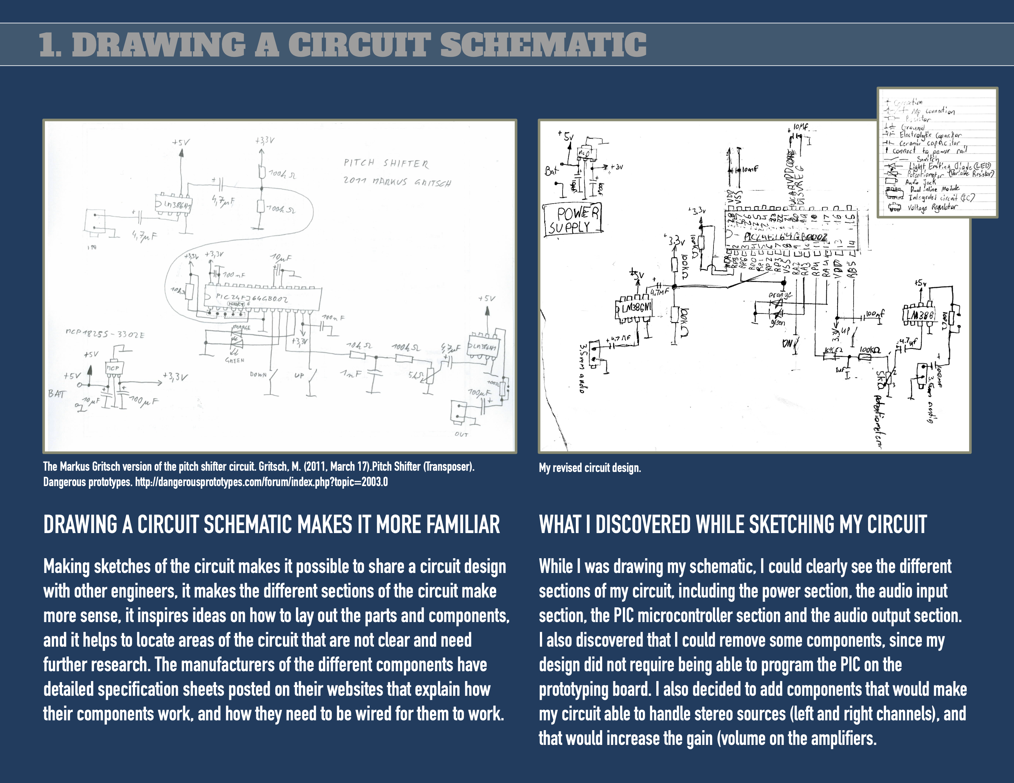
Drawing a circuit schematic makes it more familiar
Making sketches of the circuit makes it possible to share a circuit design with other engineers, it makes the different sections of the circuit make more sense, it inspires ideas on how to lay out the parts and components, and it helps to locate areas of the circuit that are not clear and need further research. The manufacturers of the different components have detailed specification sheets posted on their websites that explain how their components work, and how they need to be wired for them to work.
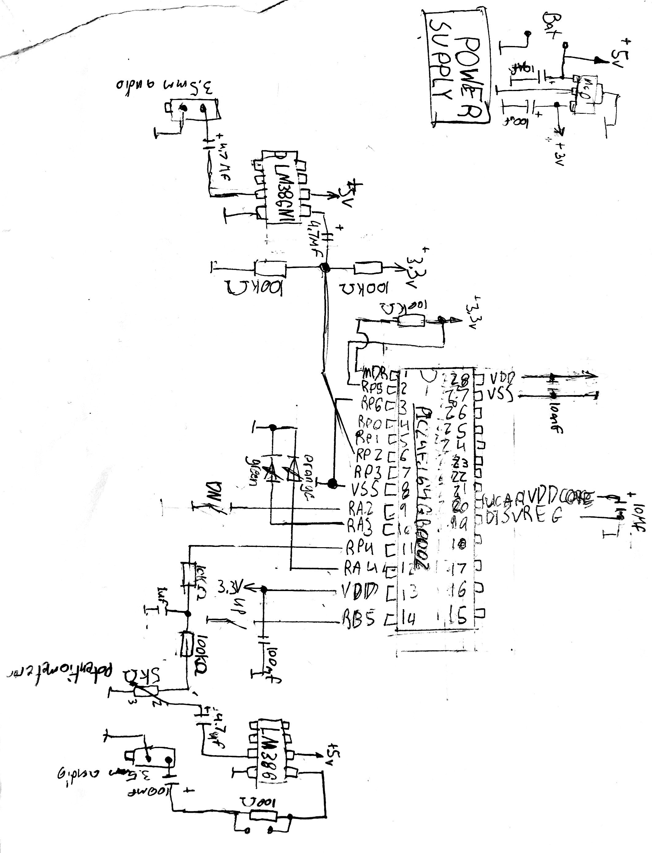
What I discovered while sketching my circuit
While I was drawing my schematic, I could clearly see the different sections of my circuit, including the power section, the audio input section, the PIC microcontroller section and the audio output section. I also discovered that I could remove some components, since my design did not require being able to program the PIC on the prototyping board. I also decided to add components that would make my circuit able to handle stereo sources (left and right channels), and that would increase the gain (volume on the amplifiers.
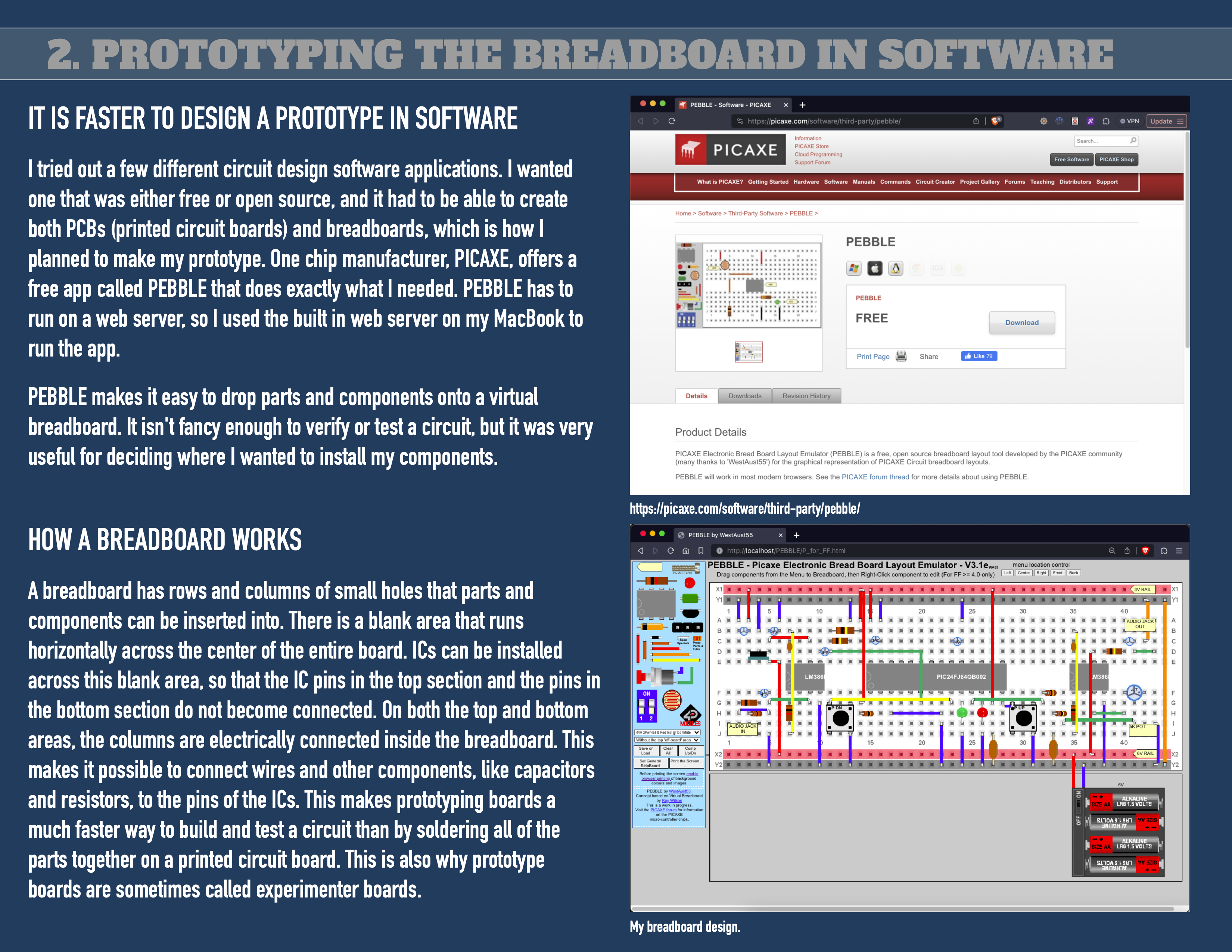
It is faster to design a prototype in software
I tried out a few different circuit design software applications. I wanted one that was either free or open source, and it had to be able to create both PCBs (printed circuit boards) and breadboards, which is how I planned to make my prototype. One chip manufacturer, PICAXE, offers a free app called PEBBLE that does exactly what I needed. PEBBLE has to run on a web server, so I used the built in web server on my MacBook to run the app.
PEBBLE makes it easy to drop parts and components onto a virtual breadboard. It isn't fancy enough to verify or test a circuit, but it was very useful for deciding where I wanted to install my components.
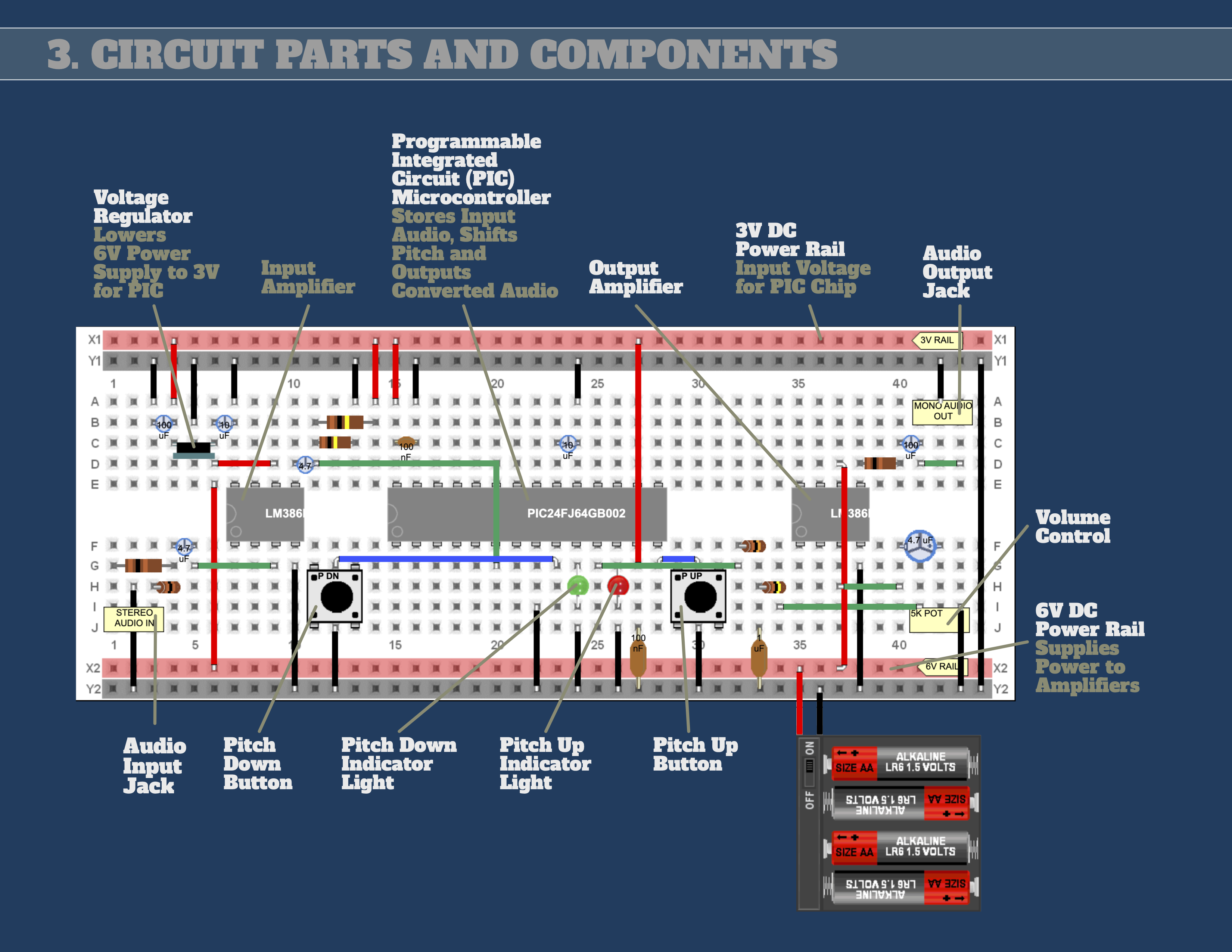
How a breadboard works
A breadboard has rows and columns of small holes that parts and components can be inserted into. There is a blank area that runs horizontally across the center of the entire board. ICs can be installed across this blank area, so that the IC pins in the top section and the pins in the bottom section do not become connected. On both the top and bottom areas, the columns are electrically connected inside the breadboard. This makes it possible to connect wires and other components, like capacitors and resistors, to the pins of the ICs. This makes prototyping boards a much faster way to build and test a circuit than by soldering all of the parts together on a printed circuit board. This is also why prototype boards are sometimes called experimenter boards.
Keep track of your parts with a list
It is important to stay very organized when designing a circuit. All of the needed parts have to be ready when it's time to build your circuit. The best way to do this is to create a list to keep track of all of the needed parts, and whether you have them.
If you need parts, there are many online electronics supply stores. I had to order many of the parts and components that I needed for my circuit. As I ordered each part and received it, I checked it off on my list.
Using my list, I also kept track of how many of each part or component I needed, what it's purpose was in the circuit, and where I ordered it from.
This list is also useful if I ever want to make more copies of my circuit, for example, if I decided that I wanted to manufacture and sell my pitch shifter. I would be able to use the list to order more parts, and also to figure out how much each copy of my circuit would cost to make.
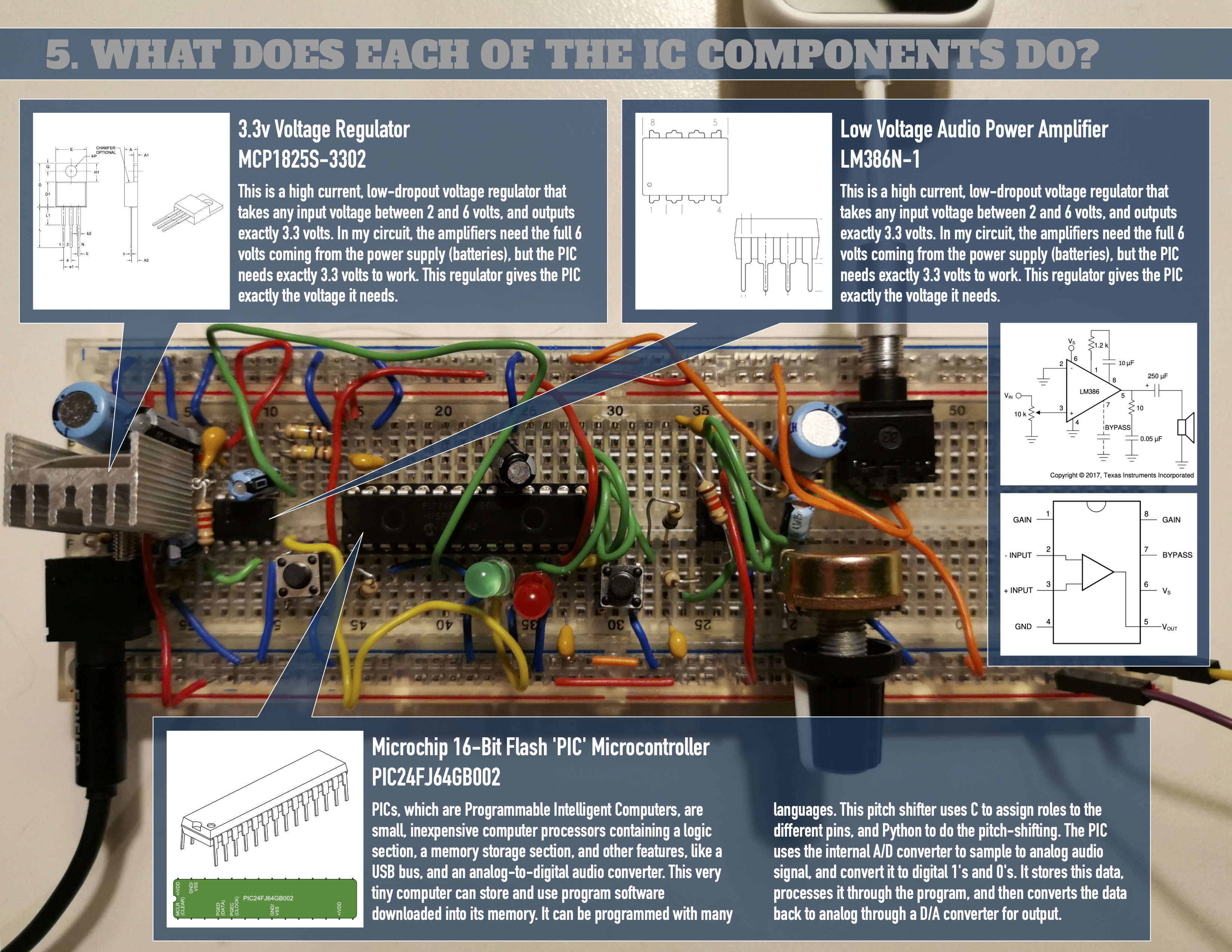
What does each of the IC components do?
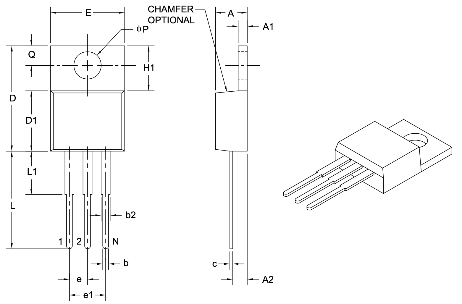
3.3v Voltage Regulator MCP1825S-3302
This is a high current, low-dropout voltage regulator that takes any input voltage between 2 and 6 volts, and outputs exactly 3.3 volts. In my circuit, the amplifiers need the full 6 volts coming from the power supply (batteries), but the PIC needs exactly 3.3 volts to work. This regulator gives the PIC exactly the voltage it needs.
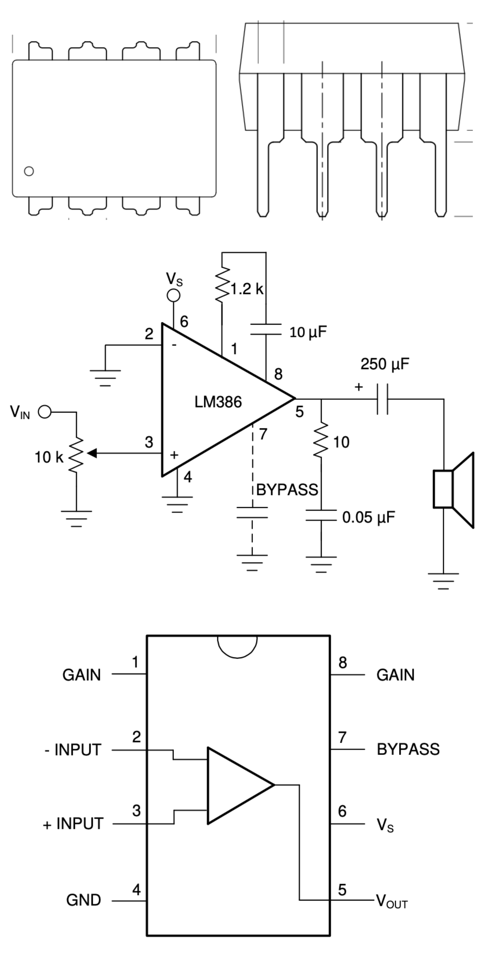
Low Voltage Audio Power Amplifier LM386N-1
This is a high current, low-dropout voltage regulator that takes any input voltage between 2 and 6 volts, and outputs exactly 3.3 volts. In my circuit, the amplifiers need the full 6 volts coming from the power supply (batteries), but the PIC needs exactly 3.3 volts to work. This regulator gives the PIC exactly the voltage it needs.
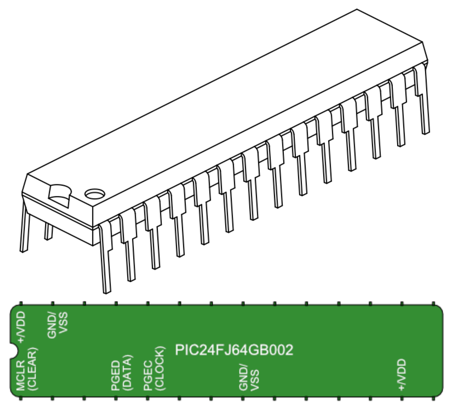
Microchip 16-Bit Flash 'PIC' Microcontroller PIC24FJ64GB002
Programmable Integrated Circuit (PIC) microcontrollers, made by Microchip Technology, are integrated chips consisting of CPU, RAM, timer, ROM, and counter. PIC microcontrollers are widely used in various applications due to their ease of programming, interfacing, wide availability, lower cost, serial programming capability, and extensive user base.
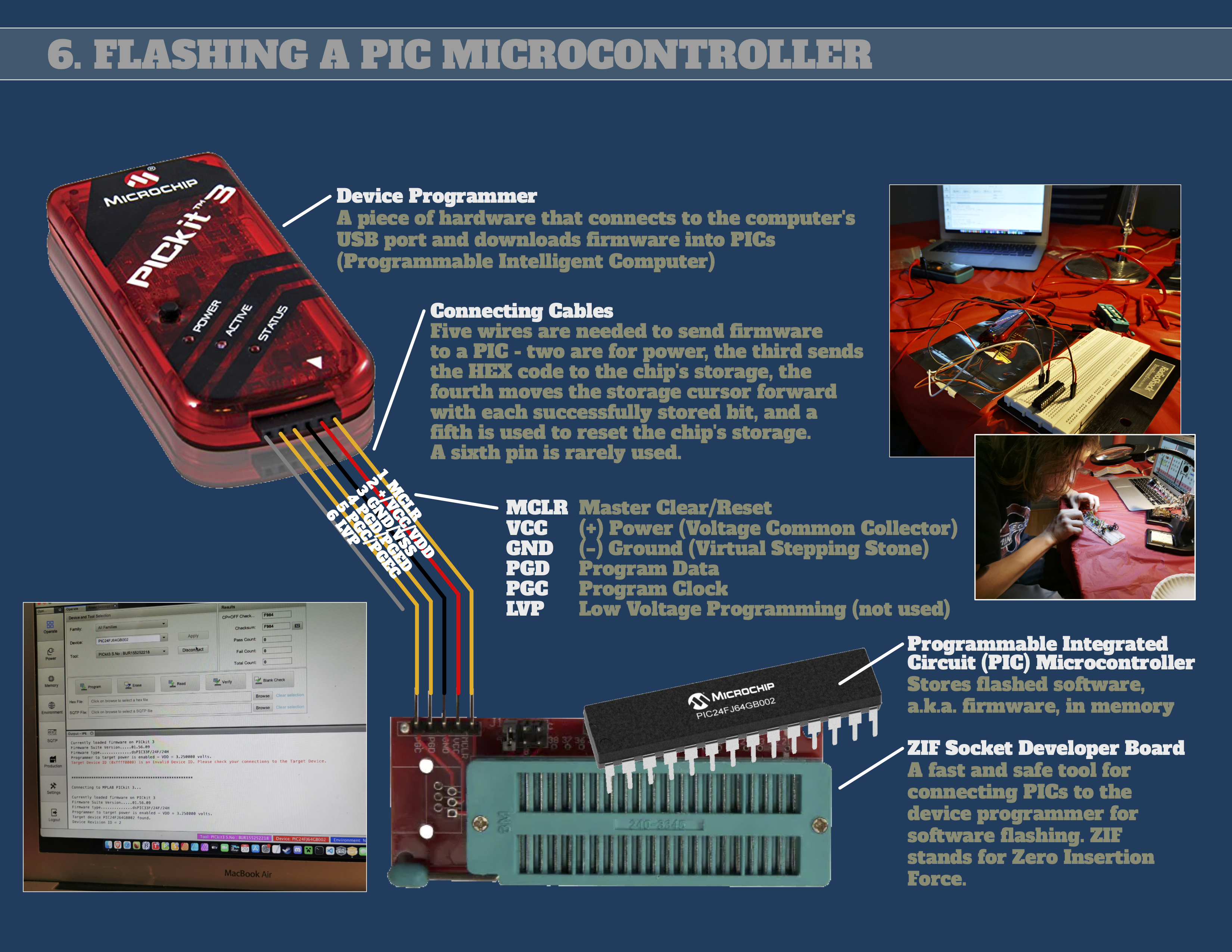
Flashing a PIC microcontroller
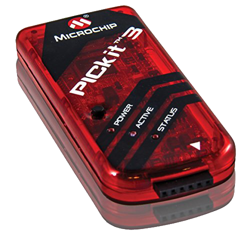
Device programmer and connecting cables
A piece of hardware that connects to the computer's USB port and downloads firmware into PICs (Programmable Intelligent Computer)
Five wires are needed to send firmware to a PIC - two are for power, the third sends the HEX code to the chip's storage, the fourth moves the storage cursor forward with each successfully stored bit, and a fifth is used to reset the chip's storage. A sixth pin is rarely used.
| MCLR | Master Clear/Reset |
|---|---|
| VCC (+) | Power (Voltage Common Collector) |
| GND (-) | Ground (Virtual Stepping Stone) |
| PGD | Program Data |
| PGC | Program Clock |
| LVP | Low Voltage Programming (not used) |
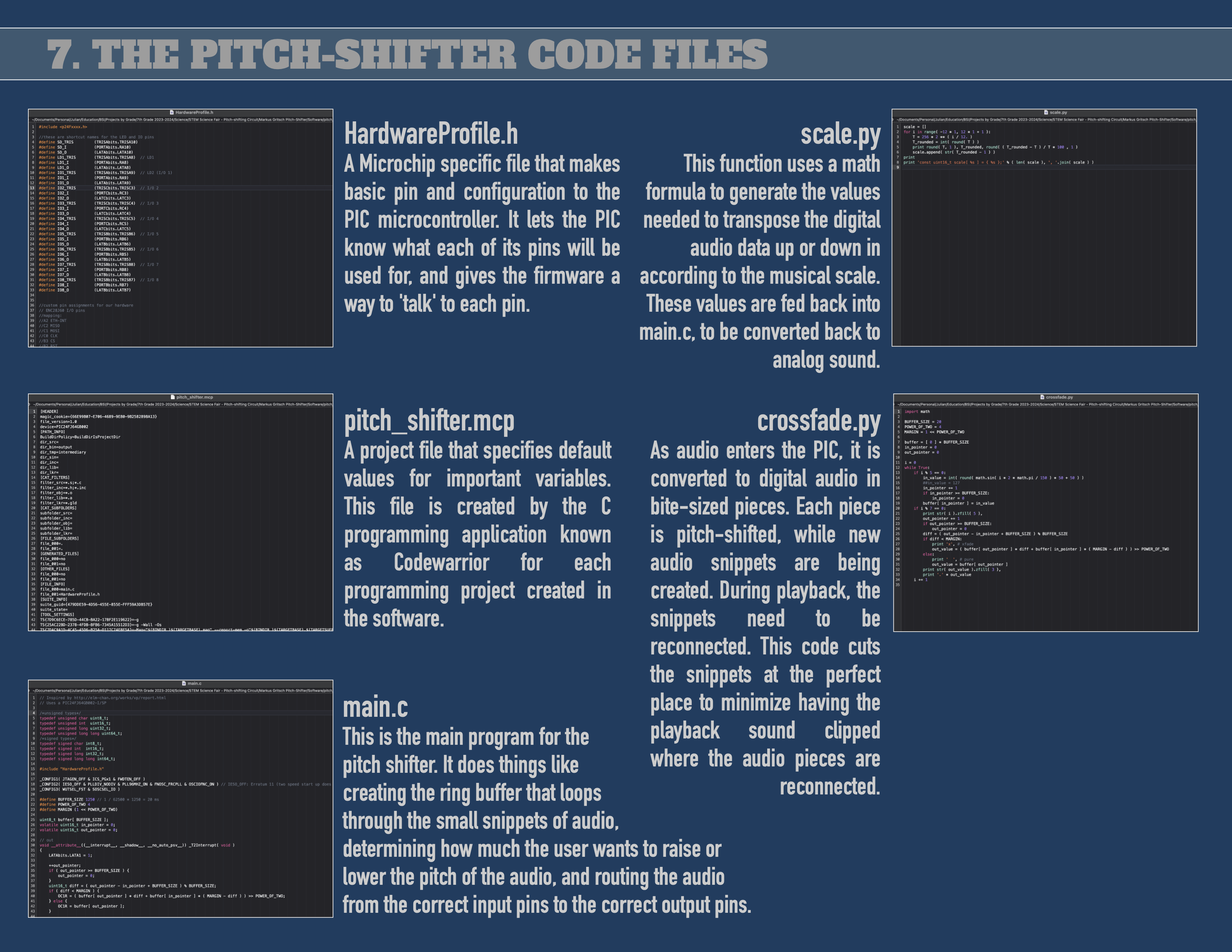
The pitch-shifter code files
The firmware code, discussed below, was created and posted by Markus Gritsch, and is available for download at dangerousprototypes.com.
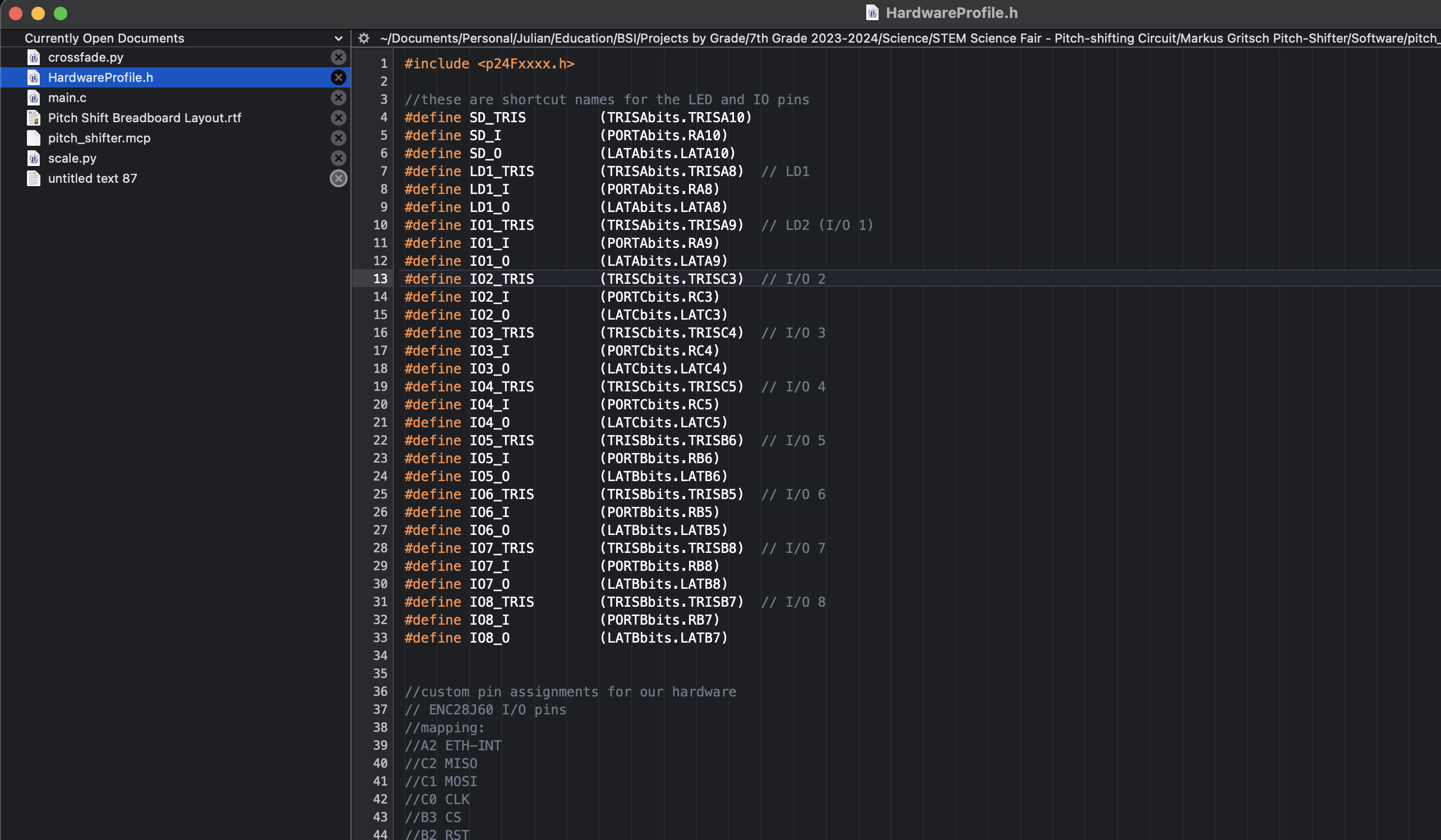
HardwareProfile.h
A Microchip specific file that makes basic pin and configuration to the PIC microcontroller. It lets the PIC know what each of its pins will be used for, and gives the firmware a way to 'talk' to each pin.
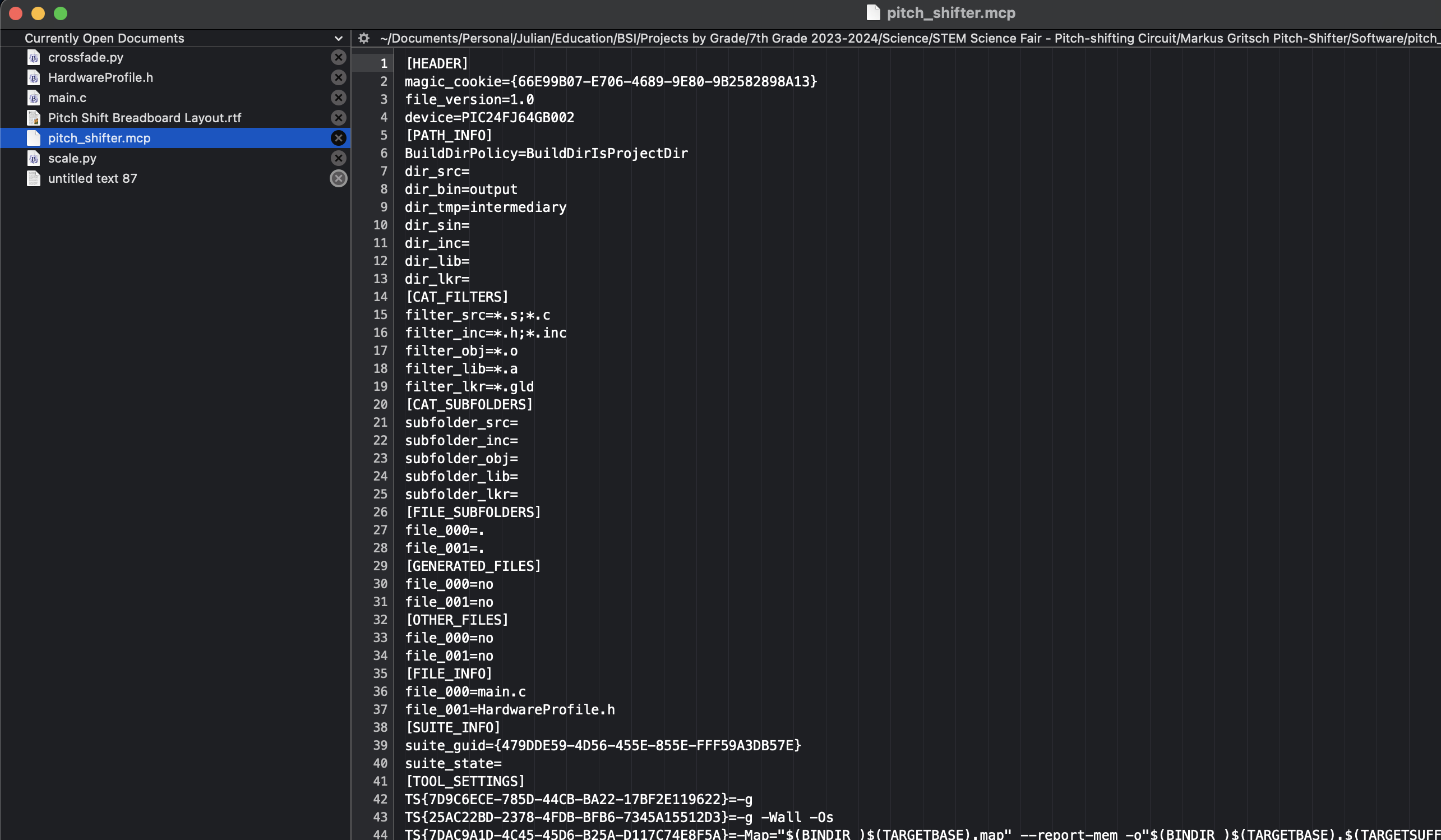
pitch_shifter.mcp
A project file that specifies default values for important variables. This file is created by the C programming application known as Codewarrior for each programming project created in the software.
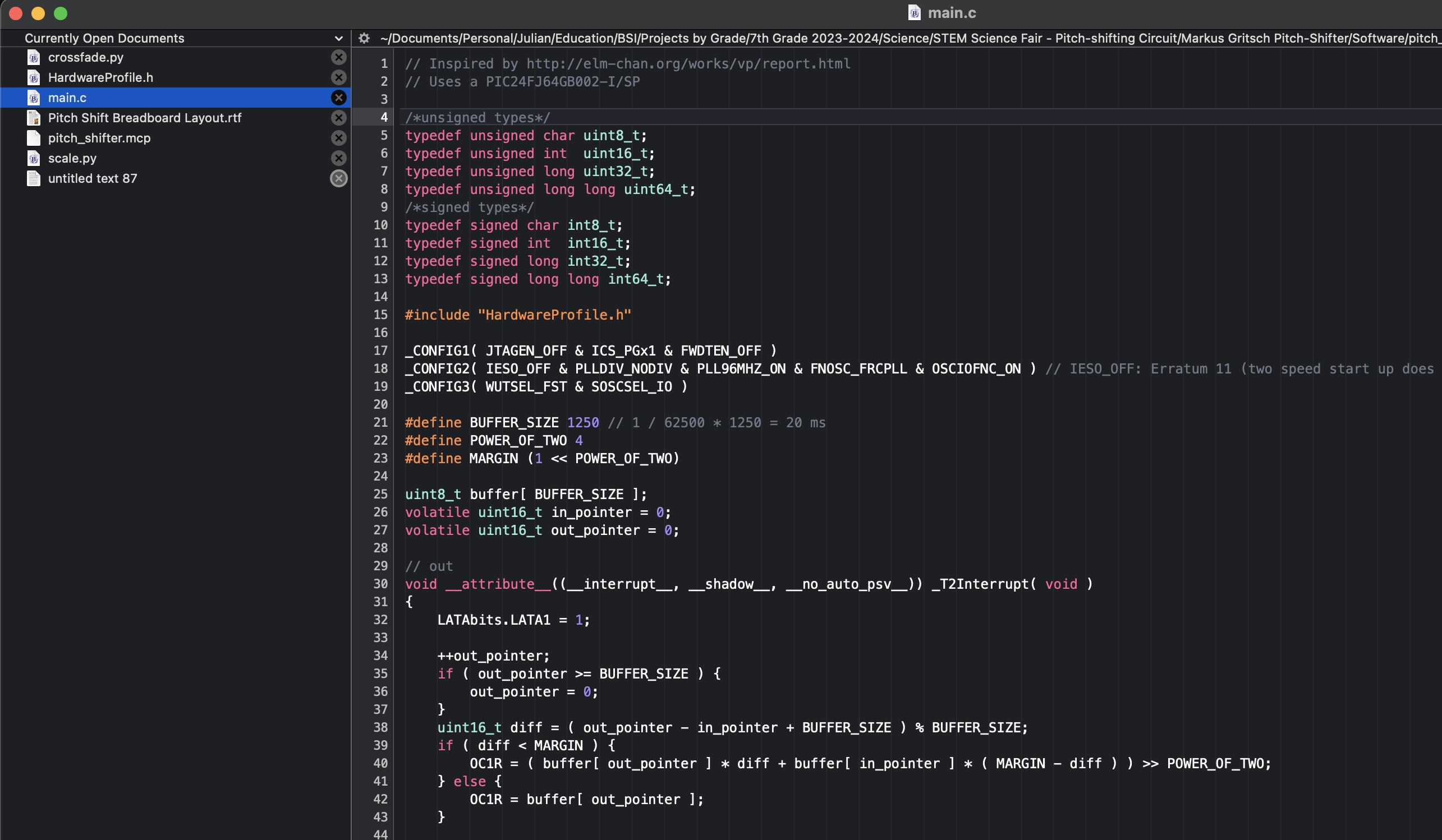
main.c
This is the main program for the pitch shifter. It does things like creating the ring buffer that loops through the small snippets of audio, determining how much the user wants to raise or lower the pitch of the audio, and routing the audio from the correct input pins to the correct output pins.
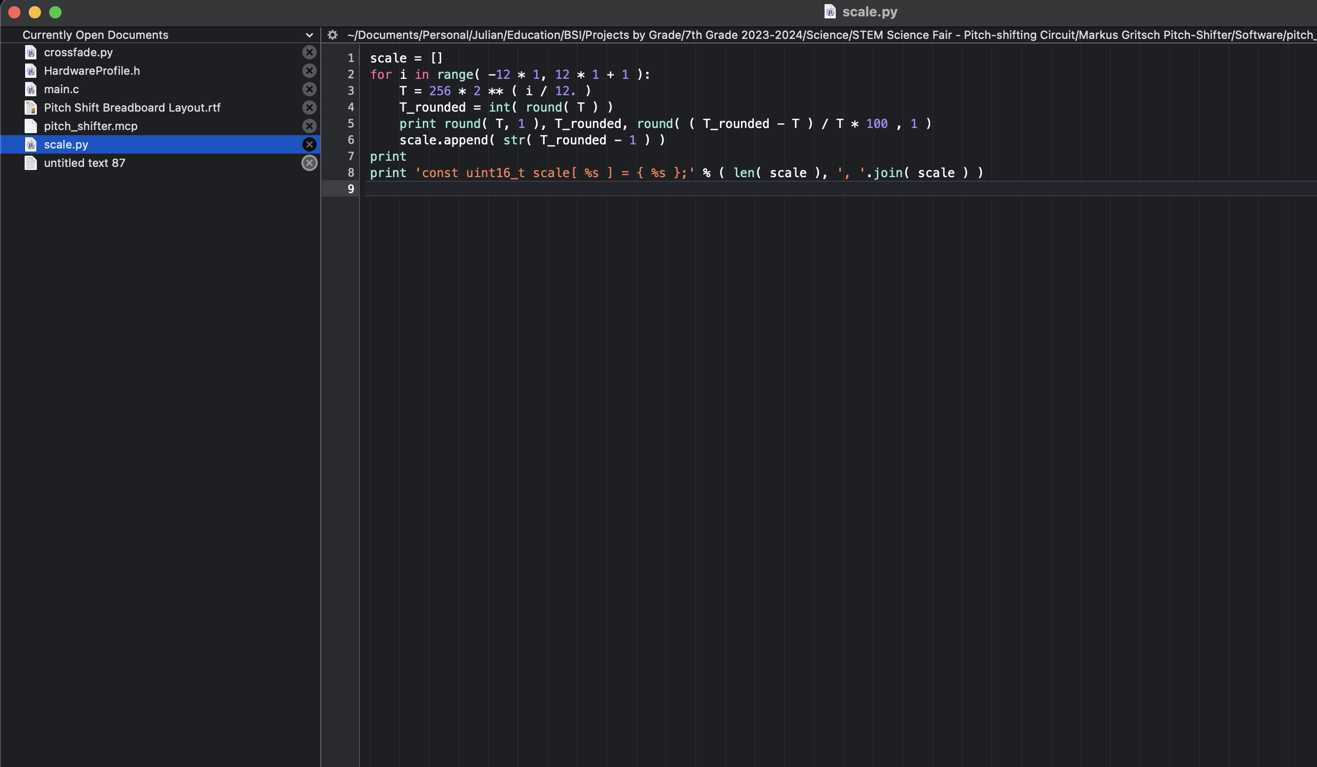
scale.py
This function uses a math formula to generate the values needed to transpose the digital audio data up or down in according to the musical scale. These values are fed back into main.c, to be converted back to analog sound.
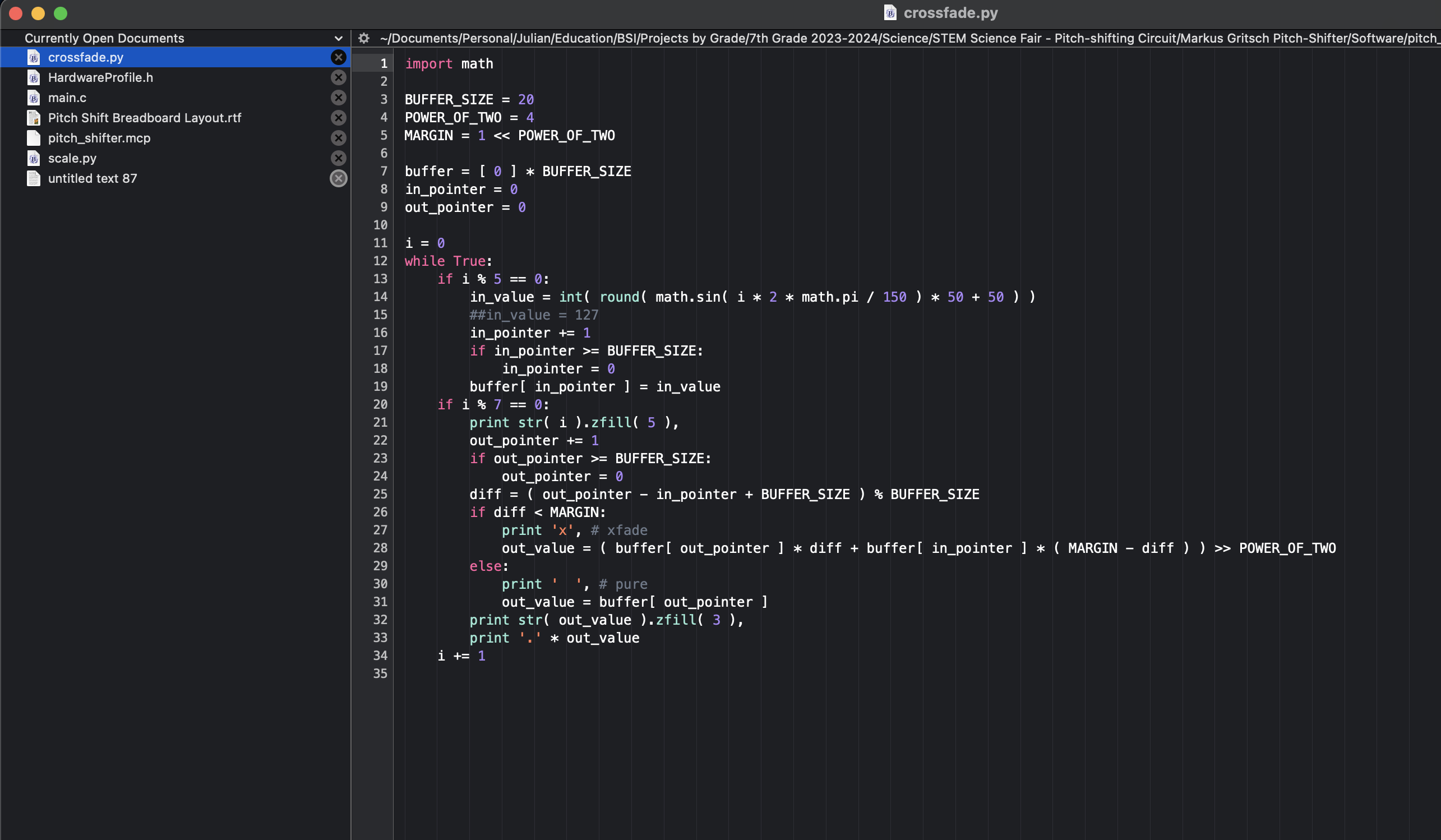
crossfade.py
As audio enters the PIC, it is converted to digital audio in bite-sized pieces. Each piece is pitch-shifted, while new audio snippets are being created. During playback, the snippets need to be reconnected. This code cuts the snippets at the perfect place to minimize having the playback sound clipped where the audio pieces are reconnected.
Debugging
When I powered up my circuit for the first time, it did not work. It just made buzzing sounds. I had to disconnect all of the most sensitive ICs, so that they would not get damaged while I tested each section of my circuit board. First, I attached a speaker to the end of my audio input circuit. Here, I discovered that I had incorrectly connected my input amp. I fixed this, and tested the circuit again. It still didn't work, so I tested the power section with a multimeter and a component tester. This was working correctly, but was only powering half of each positive voltage rail. I added extra wires to bring power to the unconnected parts of the power rails.
Next, I tested the output audio section. This part was working correctly. Next, I tested my microprocessor. It was programmed correctly, but was not turning on. I realized that I needed to add power to one pin that I didn't realize needed power. This time, when I tested my circuit music started coming out. When I pressed the pitch up button and the sound's pitch changed, I knew my circuit had come to life
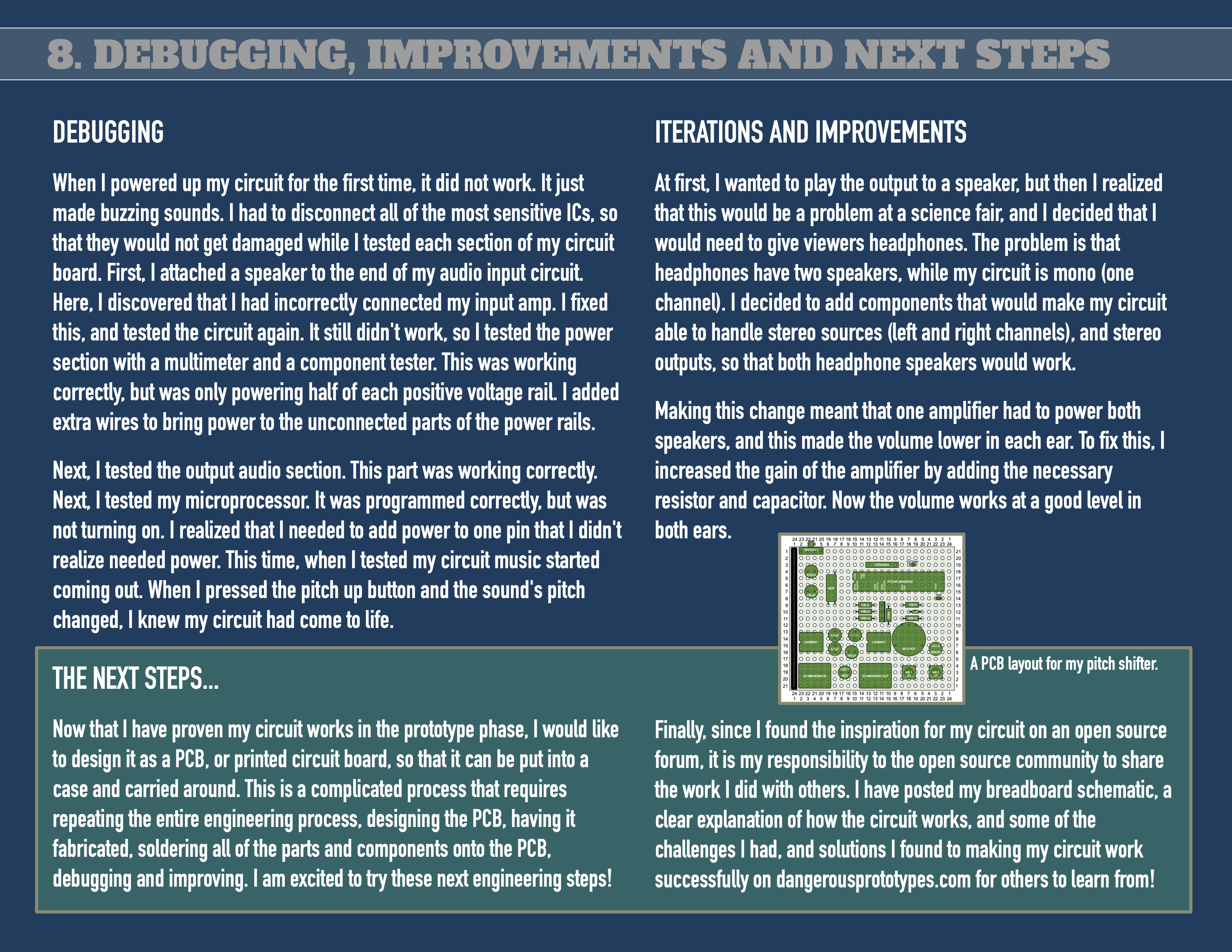
Iterations and improvements
At first, I wanted to play the output to a speaker, but then I realized that this would be a problem at a science fair, and I decided that I would need to give viewers headphones. The problem is that headphones have two speakers, while my circuit is mono (one channel). I decided to add components that would make my circuit able to handle stereo sources (left and right channels), and stereo outputs, so that both headphone speakers would work.
Making this change meant that one amplifier had to power both speakers, and this made the volume lower in each ear. To fix this, I increased the gain of the amplifier by adding the necessary resistor and capacitor. Now the volume works at a good level in both ears.
The next steps...
Now that I have proven my circuit works in the prototype phase, I would like to design it as a PCB, or printed circuit board, so that it can be put into a case and carried around. This is a complicated process that requires repeating the entire engineering process, designing the PCB, having it fabricated, soldering all of the parts and components onto the PCB, debugging and improving. I am excited to try these next engineering steps!
Circuit Board Design
This is my first attempt at designing a circuit layout for the pitch shifter. I used a graphic design program for this, but I next plan to lay this out in a proper piece of PCB design software.
Finally, since I found the inspiration for my circuit on an open source forum, it is my responsibility to the open source community to share the work I did with others. I have posted my breadboard schematic, a clear explanation of how the circuit works, and some of the challenges I had, and solutions I found to making my circuit work successfully on dangerousprototypes.com for others to learn from. I have also posted my process and discoveries here! Hope you've found them helpful if you're also trying to learn the basics of circuit building!
Sources
My preliminary schematic, based on a project posted to DangerousPrototypes.com
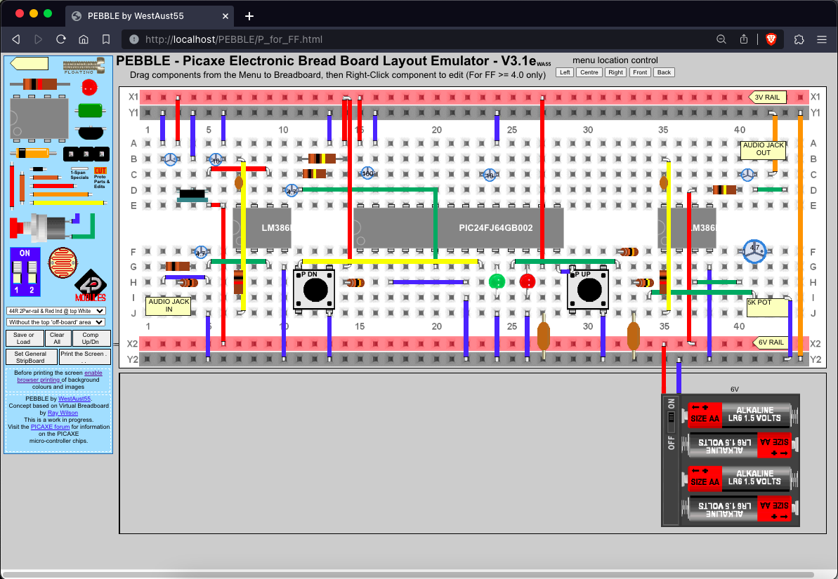
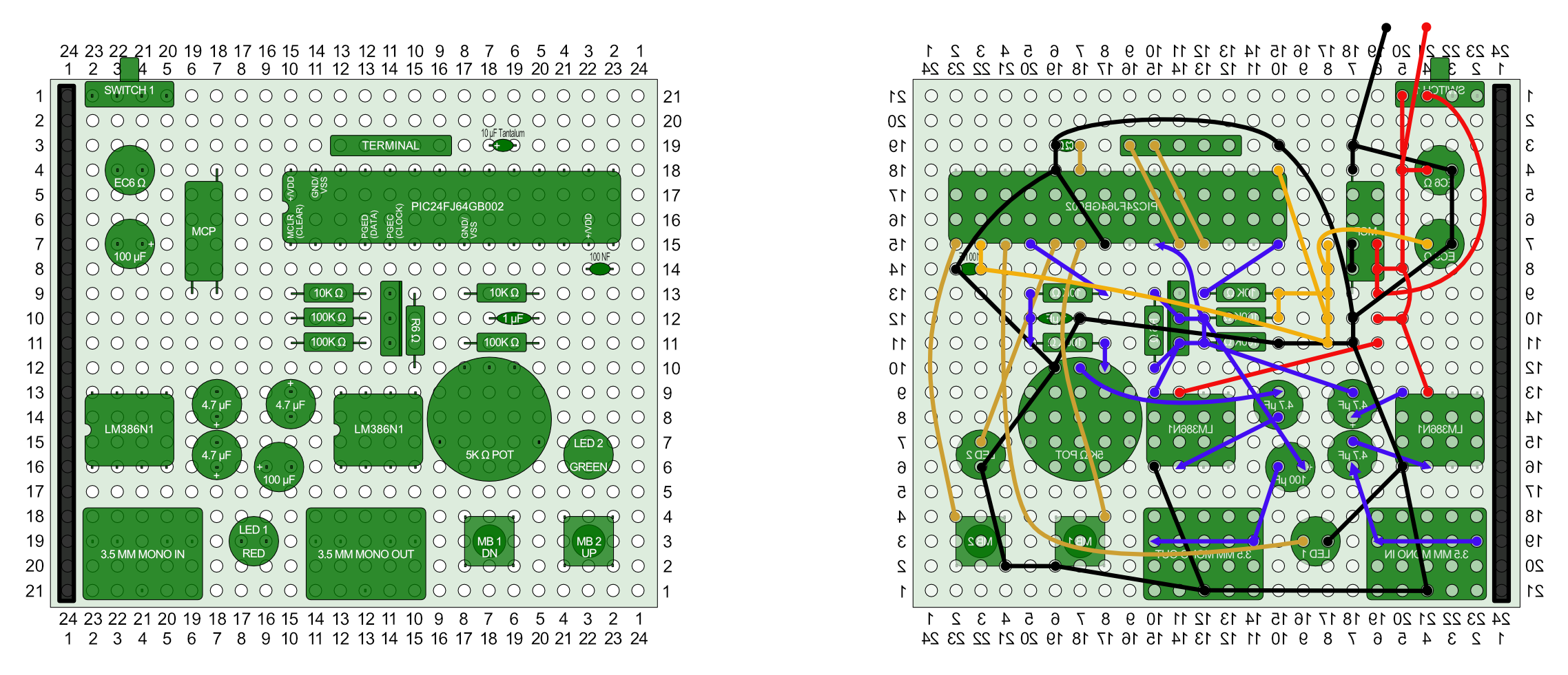
My prototype breadboard design, made using Picaxe's freely offered, and extremely useful Pebble breadboard design application.
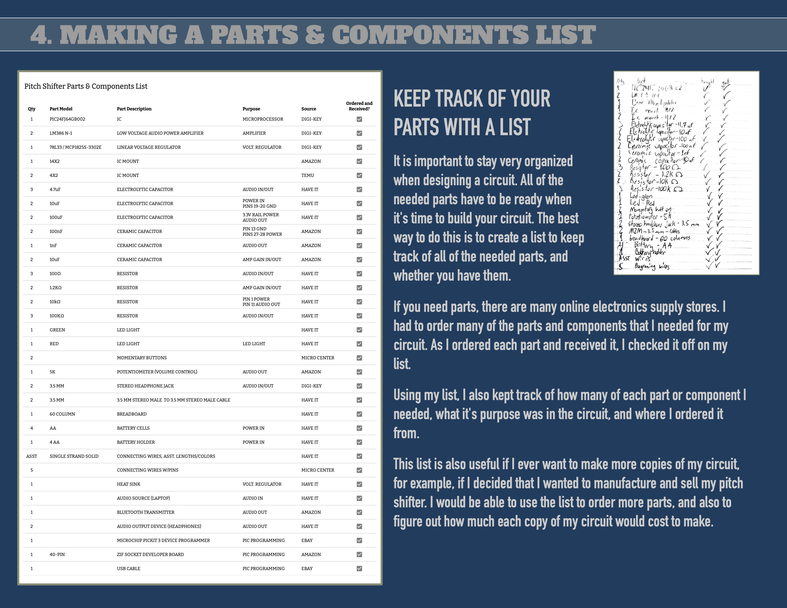
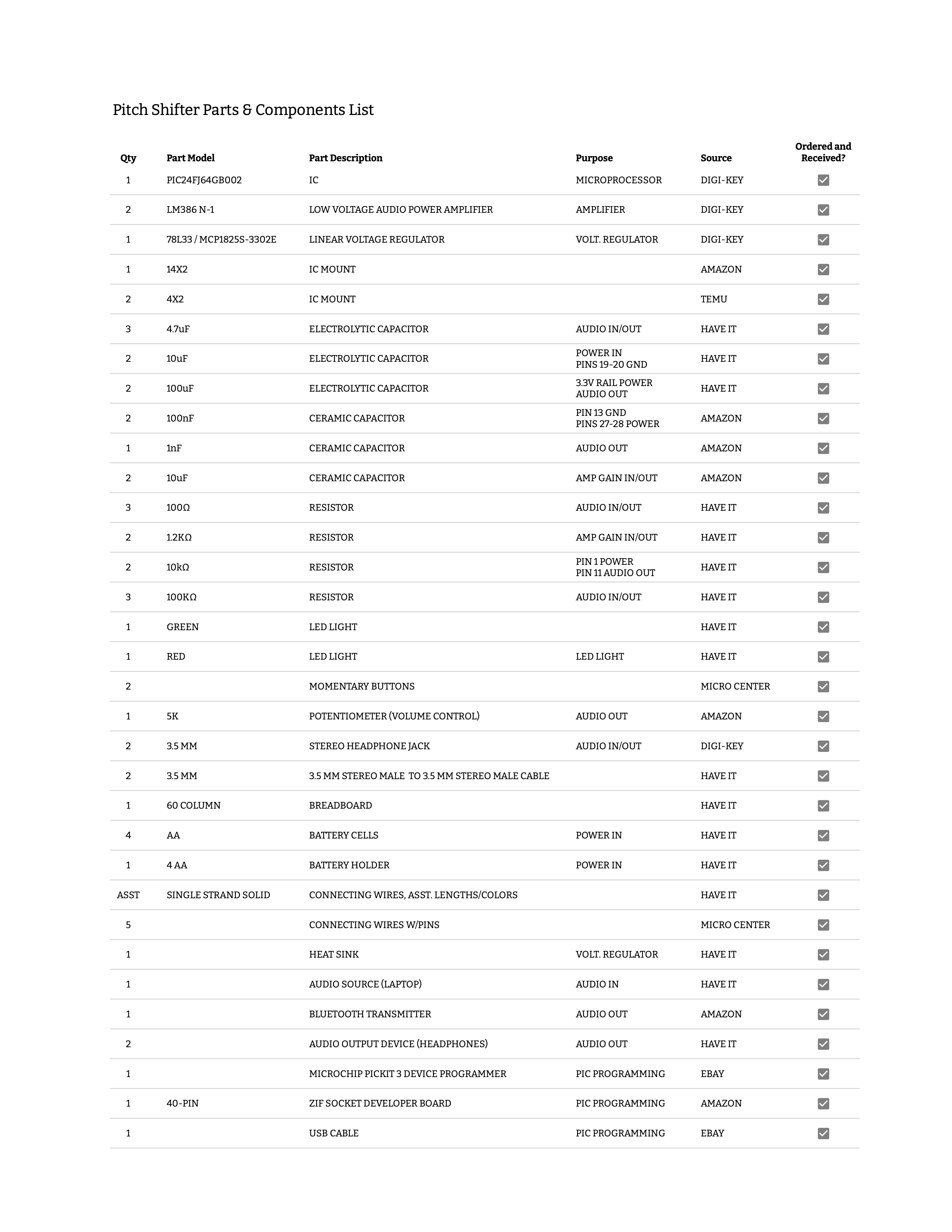
A full parts list, with required quantities of each item.